
Before rushing into the applications of wavelet analysis, a brief
expose on some of the basic concepts that make wavelet analysis
such a useful signal processing tool shall be presented. It is
not the purpose of this article to provide a detailed mathematical
foundation for wavelets, but instead to enable the reader to grasp
the underlying features that make wavelets one of the most exciting
research areas in signal processing today. Wavelet analysis is
similar to Fourier analysis in the sense that it breaks a signal
down into its constituent parts for analysis. Whereas the Fourier
transform breaks the signal into a series of sine waves of different
frequencies, the wavelet transform breaks the signal into its
"wavelets", scaled and shifted versions of the "mother
wavelet". There are however some very distinct differences
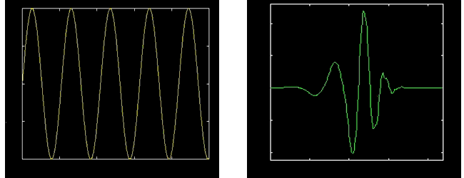
as is evident in Figure 1, which compares a sine wave to the Debauchies
5 wavelet. In comparison to the sine wave which is smooth and
of infinite length, the wavelet is irregular in shape and compactly
supported. It is these properties of being irregular in shape
and compactly supported that make wavelets an ideal tool for analysing
signals of a non-stationary nature. Their irregular shape lends
them to analysing signals with discontinuity's or sharp changes,
while their compactly supported nature enables temporal localisation
of a signals features.

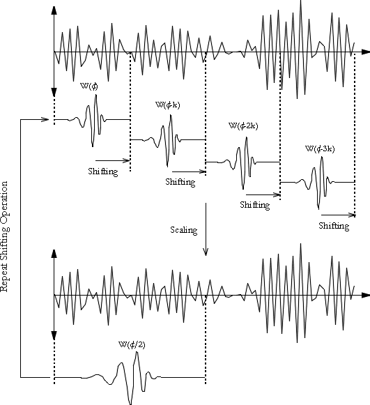
When analysing signals of a non-stationary nature, it is often beneficial to be able to acquire a correlation between the time and frequency domains of a signal. The Fourier transform, provides information about the frequency domain, however time localised information is essentially lost in the process. The problem with this is the inability to associate features in the frequency domain with their location in time, as an alteration in the frequency spectrum will result in changes throughout the time domain. In contrast to the Fourier transform, the wavelet transform allows exceptional localisation in both the time domain via translations of the mother wavelet, and in the scale (frequency) domain via dilations [VIDA91]. The translation and dilation operations applied to the mother wavelet are performed to calculate the wavelet coefficients, which represent the correlation between the wavelet and a localised section of the signal. The wavelet coefficients are calculated for each wavelet segment, giving a time-scale function relating the wavelets correlation to the signal. This process of translation and dilation of the mother wavelet is depicted below in Figure 2.

It should be noted that the process examined here is the DWT, where the signal is broken in to dyadic blocks (shifting and scaling is based on a power of 2). The continuous wavelet transform (CWT) still uses discretely sampled data, however the shifting process is a smooth operation across the length of the sampled data, and the scaling can be defined from the minimum (original signal scale) to a maximum chosen by the user, thus giving a much finer resolution. The trade off for this improved resolution is an increased computational time and memory required to calculate the wavelet coefficients. A comparison of the DWT and CWT representations of a noisy chirp signal with a high frequency component is shown below in Figure 3.

The effect of this shifting and scaling process is to produce a time-scale representation, as depicted in Figure 4. As can be seen from a comparison with the STFT, which employs a windowed FFT of fixed time and frequency resolution, the wavelet transform offers superior temporal resolution of the high frequency components and scale (frequency) resolution of the low frequency components. This is often beneficial as it allows the low frequency components, which usually give a signal its main characteristics or identity, to be distinguished from one another in terms of their frequency content, while providing an excellent temporal resolution for the high frequency components which add the nuance's to the signals behaviour.

The dilation function of the discrete wavelet transform can be
represented as a tree of low and high pass filters, with each
step transforming the low pass filter as shown in Figure 5. The
original signal is successively decomposed into components of
lower resolution, while the high frequency components are not
analysed any further. The maximum number of dilations that can
be performed is dependent on the input size of the data to be
analysed, with 2N data samples enabling the breakdown of the signal
into N discrete levels using the discrete wavelet transform

The versatility and power of the DWT can be significantly increased
by using its generalised form, wavelet packet analysis (DWPA).
Unlike the DWT which only decomposes the low frequency components
(approximations), DWPA utilises both the low frequency components
(approximations), and the high frequency components (details).
Figure 6 shows the wavelet decomposition tree.

DWPA allows the signal to be decomposed into any of 2N different
signal encoding schemes. Choosing the optimum scheme for a particular
signal is usually achieved by determining the best basis for the
tree, normally through an entropy based criterion [MISI96]. The
same noisy chirp is depicted in Figure 7 is shown below in terms
of its best basis wavelet packet analysis. As it is clearly evident,
wavelet packet analysis offers superior resolution and clarification
of details about the signal. The best basis criterion used in
the example was the Shannon entropy criterion.
